Austral Oil Engines
Ronaldson Bros. & Tippett – Austral Oil Engines
The Austral Oil Engine was made in many different sizes with quite a few different varients.
From portable to stationary, hopper cooled to tank cooled, lamp start and then later magneto start.
Below are a range of engines manufacture by Ronaldson Tippett in the 1920s.
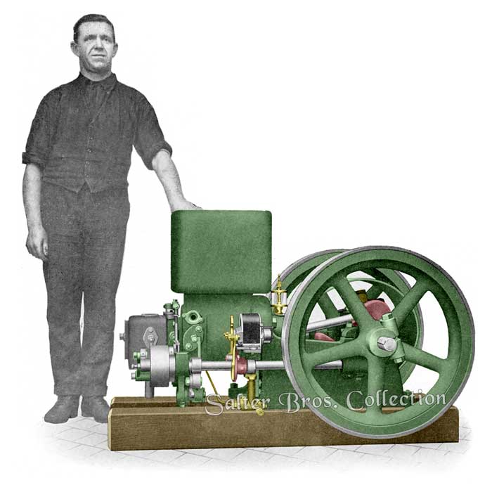
3 B.H.P. Stationary Hopper Cooled Kerosene Engine
(Largely used throughout Australia for driving milking plants)
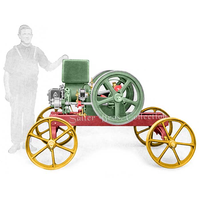
3 B.H.P. Portable Hopper Cooled Kerosene Engine
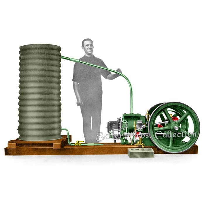
3 B.H.P. Stationary Tank Cooled Kerosene Engine
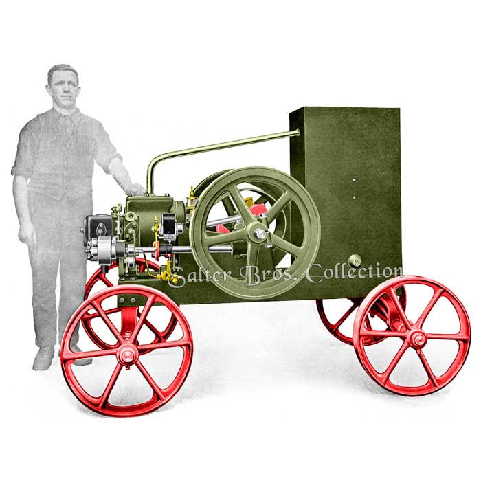
3 B.H.P. Portable Tank Cooled Kerosene Engine
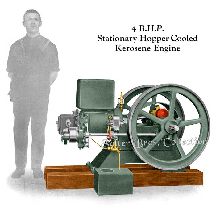
4 B.H.P. Stationary Hopper Cooled Kerosene Engine
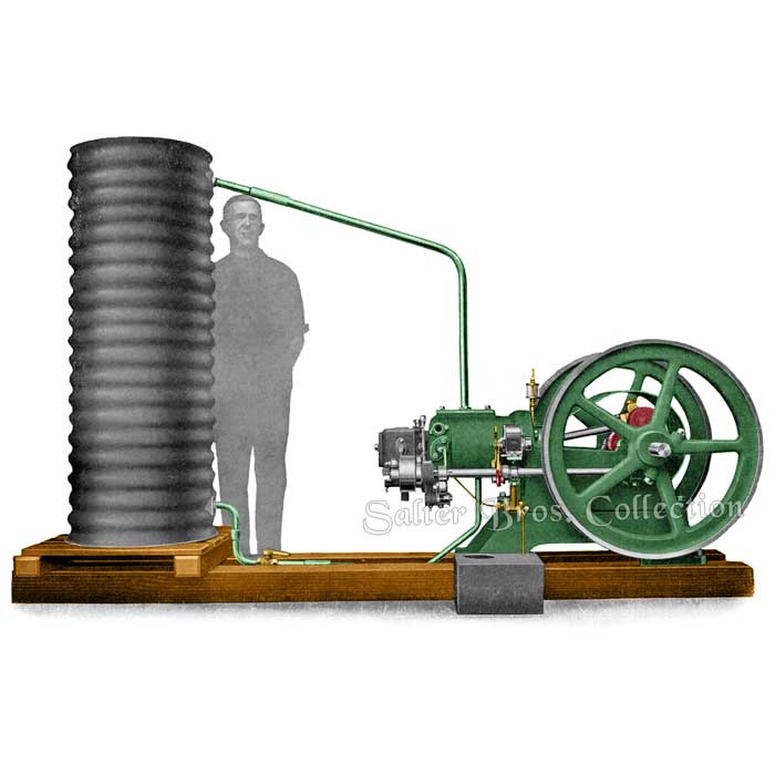
4 B.H.P. Stationary Tank Cooled Kerosene Engine
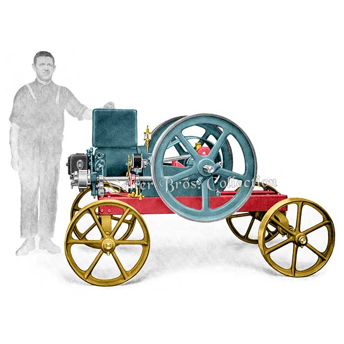
3 B.H.P. Portable Hopper-Cooled Kerosene Engine
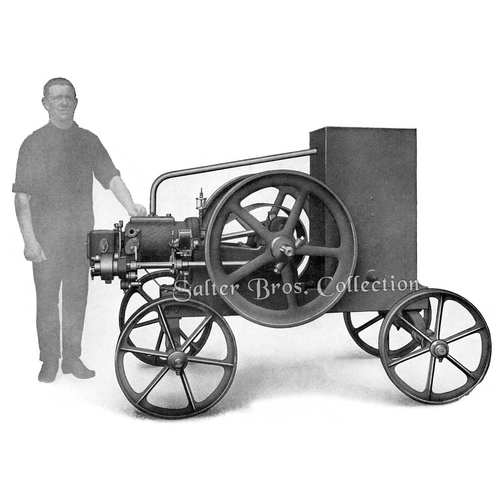
4 B.H.P. Portable Tank Cooled Kerosene Engine
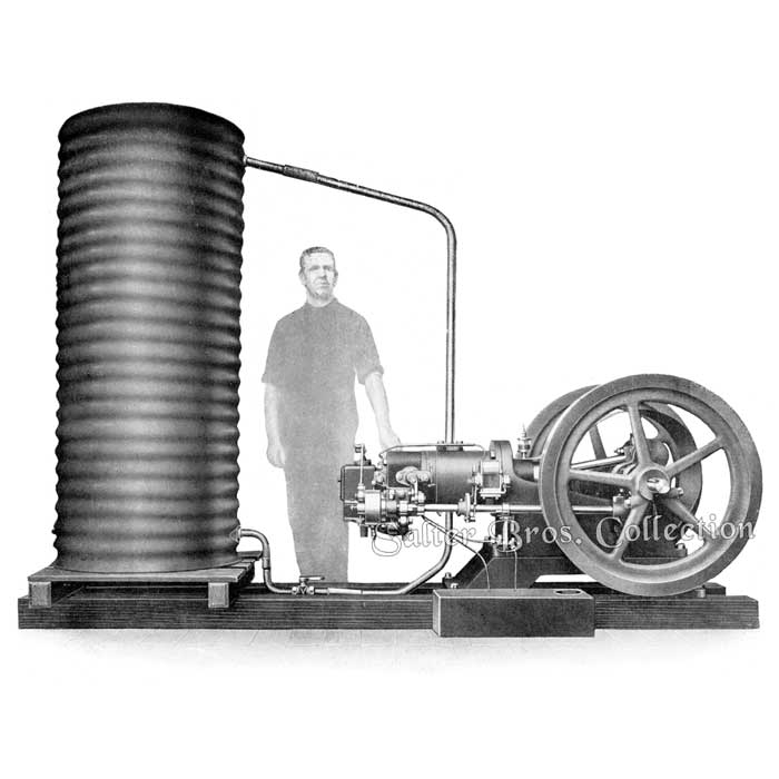
5 B.H.P. Stationary Tank Cooled Kerosene Engine
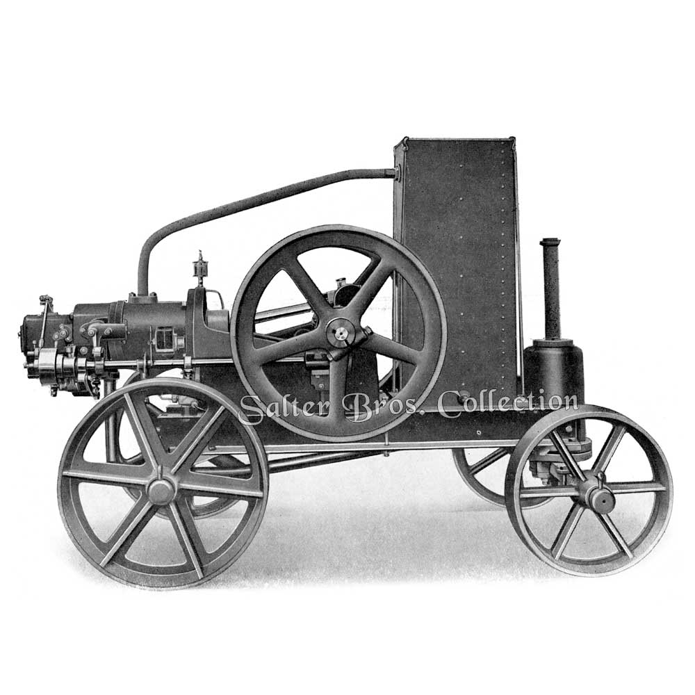
5 B.H.P. Portable Tank Cooled Kerosene Engine
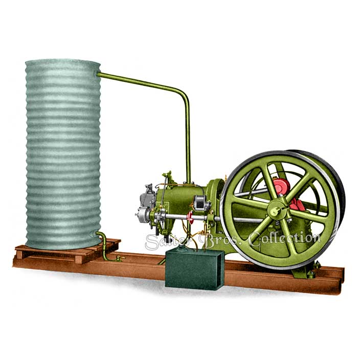
6, 7 and 8 B.H.P. Stationary Tank Cooled Kerosene Engine
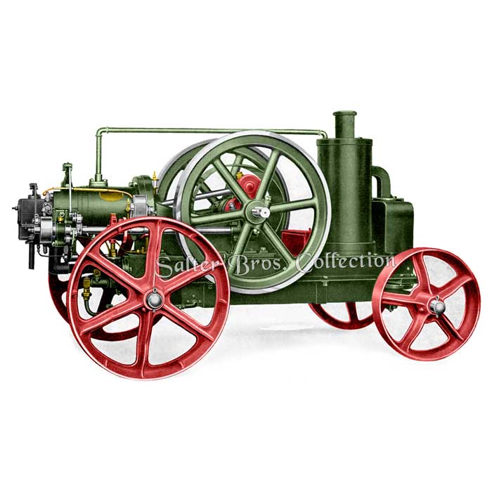
6, 7 and 8 B.H.P. Portable Tank Cooled Kerosene Engine
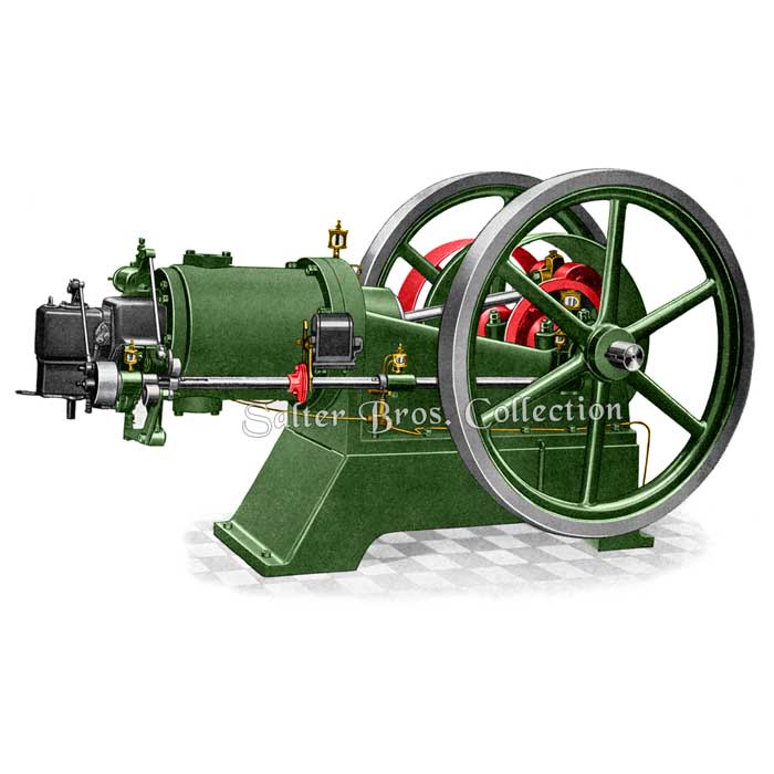
11, 16 and 20 B.H.P. Stationary Tank Cooled Kerosene Engine
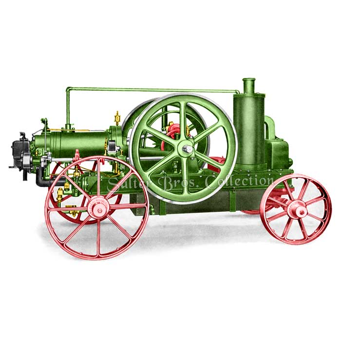
11, 16 and 20 B.H.P. Portable Tank Cooled Kerosene Engine
From the Furnace to the Farm
The “Ronaldson-Tippett” Kerosene Engine, with the exception of magnetos and Lubricators, is built wholly in our own factory at Ballarat, the largest Internal Combustion Engine factory in the Southern Hemisphere.
The following illustrations are given with the idea of showing the quality, materials and methods used in their manufacture. We might state that during the last few years we have spent several thousands of pounds in improving our buildings and plant, and placing our systems and methods on the most modern basis. Our organisation is so planned that every man in our works runs on schedule. Each man can concentrate on the work allotted to him without delays and interruptions, resulting in the greatest output at the least cost. From the first operation – the smelting of the iron in the furnaces-right to the actual testing of the finished engine before delivery, only the very latest and modern methods of production are used.

1. The beginning of an Engine. Here is shown some pig iron, a little of which is imported from Scotland, but the greater quantity is obtained from Broken Hill, which is world famous for its quality iron ore.

2. The blast furnace from which 30 tons of castings are turned out each week, including iron and semi-steel. This picture shows the molten metl running from the furnace.

3. Showing the running of crucible cast steel from the crucible to the mould. Eceedingly high temperatures are reached in the production of crucible steel.

4. Here are shown samples of, at the top, nickel iron, and underneath, good cast iron. Look at the wonderful closeness of the grain in the nickel iron – which is used in our cylinders and pistons, giving two to three times the ordinary life.

5. The first operation is molding a flywheel casting. After the pattern has been removed, the mould is polished and finished with plumbago; then the molten metal is poured in.

6. After castings are taken from the moulds they are placed in large rumblers like this. The barrel revolves, automatically cleaning the castings of all sand.

7. This is one of the Planing Machines, carrying Engine beds, inverted so that the planer can machine the bottom surfaces.

8. The Engine bed is on more than one occasion setup under a Radial Drill, shown here. This machine has a radial arm which allows of the drill being swung to any position.

9. Here you see a lathe designed and made by us for turning flywheels. This machine can turn both sides of a flywheel and face it in the one operation.

10. This is a lathe roughing Pistons before they are finally finished. You will notice the grooves cut in the piston to take the rings.

11. Here is one of our many turret lathes for all classes of small standardised parts. This machine represents the very latest in plant, and turns out work with wonderful accuracy.

12. This lathe is used solely for turning crankshafts, and as the operator has been on this job or several years you will understand that he has become expert at his job.

13. Here is a profile grinder grinding up cams to standard template. Our cams are of special steel, bored, ground and hardened.

14. One of the latest hack saws, capable of sawing a 2 ½ inch shaft through in two minutes.

15. Here is the inspection bench, where all machined parts are tested and gauged before being passed. Rigid inspections ensures a very high standard throughout.

16. All our connecting rods are of mild steel and are forged from the solid under the power hammer in the Blacksmiths’ Shop.

17. The three processes in the making of a connecting rod: First, the steel billet, then the forged rod, and finally the machined rod.

18. The Sheet Metal Department, showing a water tank being finished off after being previously rivited by an electric welding machine.

19. This illustration shows fitter assembling governors.

20. Showing an Engine in the course of completion. The vaporiser and valves have been fitted, also some of their levers and connections.

21. Every Engine is thoroughly tested before it leaves the works – not simply given a run and pushed out. Illustration shows an indicator card being taken whilst engine is under test.

22. The beginning of a lifetime of satisfactory service. Showing an Engine under actual working conditions.
Features of Design and Construction
The very fact that “Ronaldson-Tippett” Engines in every size are actually the slowest speed and strongest amongst world’s makers, places them in an incomparable position. Standards set by all the best makers have been outclassed, and an Australian Engine now proudly and rightly claims the world’s highest grade production.
Constant direct contact with Australian conditions has persistently impressed us with the necessity of making a slow speed and high grade power of great strength, Instead of yielding to the general temptation to push up speeds and cut down sizes, we have actually continued to improve our engines until to-day our position as Engine builders is unique.
Never before has a firm been able to honestly claim that every Engine built for nearly quarter of a century is still at work and giving satisfaction. Apart, however, from two fundamentals, slow speed and great strength, there are many other practical features which have been factors in making “Ronaldson-Tippett” Engines famous through Australia.
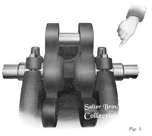

Fig. 1. Illustrates massive construction fo bed, crankshaft and main bearings. Note the great width of the crank pin to carry big end bearings.
The main bearings as well a crank shaft bearings are in phosphor bronze, ensuring the longest possible life.
Fig. 2. The bearings carrying the side shaft are made seperately and bolted to the bed and cylinder head.
Whilst this entails more work, it enables any bearing to be easily replaced in the event of accident. Consider the diffuculty where bearings are ast as part of the bed or cylinder head.
Fig. 3. Shows the cams, rollers and pins. These are not only twice a large as usually but made of special steel, case hardened, ensuring practically lifelong wear without duplicates.
Few of the world’s makers can now honestly claim case hardened parts. Many levers on our Engines are made of steel, which prevents breakages and annoying delays.
Fig. 4. Nickel iron, a scientific mixture of nickel and iron, is used in our pistons, rings and cylinders. This metal is not only twice as strong as close grained cast iron, but gives from two to three times the wearing life.
The use of nickel iron in our Engines is a factor of great importance.
Our pistons are in most cases longer than others, giving greater life. All pistons have at least four rings. Large case hardened gudgeon pins are also fitted.
Fig. 5. Our piston rings are all put through four different machine operations to ensure a perfectly round ring with a spring.
Fig. 6. All “Ronaldson-Tippett” Engines have a timing valve which controls the timing of the explosion, enabling the Engines to run more consistently and with greater economy.
Fig 7. All valves are in separate cases, so that they can, if necessary, be easily removed for machining valve seats. The advantage of this construction, although costing more, is too apparent for further comment.

Fig. 8. Valve is here shown lifted from the seat with spring relaxed.
Fig. 9. Note construction of the water pump built according to the est engineering practice. The plunger is of phosphor bronze, and has a packed gland. Both valves have large bronze balls.
These valves, we might state, cost about double that of cheaper type.
The eccentric is big and strong, whilst the connecting rod and cross pin (both case hardened) constantly work in oil.
Compare this pump with the cheaper leather-bucket type, and you will see that there is at least double the work – but our pump is a lifetime job.


Fig. 10. Shows the “Ronaldson-Tippett” Crankshaft built by our own special process.
This crank is of such great strength that we are able to guarantee it for ten years. It provides for extra big shafts and pin of special steel, preventing great wearing surfaces.
The balance weights are part of the webs, so they can never come loose and smash the engine up or do bodily harm to its owners.


An Engine may be very well consstructed, but if the system is wrong, all the time and money spent in construction goes for very little.
In most Kerosene Engine sthe kerosene is sucked or pumped into the Engine in its liquid form.
In our Engine all the kerosene is formed into a vapour gas, with a certain proportion of air, before it enters the internal working part of the Engine. By striking the vapour valve at the wrong time, kerosene gas within the vaporiser walls is driven out.
Fig. 11. Shows a cloud of kerosene vapour gas being emitted. Taking in the charge in the form of gas instead of liquid kerosene ensures what we call perfect combustion, and provides for every particle of kerosene which is taken into the Engine being used for power.
If this is done, it stands to reason that the kerosene consumption cannot be lower.

With an Engine which explodes every particle of kerosene taken in, no carbon deposits in the piston or vaporiser are formed, therefore no gritty carbon is deposited on pistons to cause undue wear.
If you look at any “Ronaldson-Tippett” Engine working you will see that the piston is clean and the exhaust perfectly clear, which is the est guarantee of a good working system.
Fig. 12. Our machine cut worm on skew gears is not only made in semi-steel, but is twice as big as usual, resulting in practically unlimited life.
Note also that the bearing carrying these gears is bolted to the ed, and that the side shaft carring gears is of an unusually large size.
(Photo. taken from 6 h.p. – Side-shaft size 1 ½ in. diam.)
Fig. 13. Our governor ensures perfectly steady running under all conditions. There is no perceptible difference in speed when an immediate veriation is made from ful load to no load.
Ten different speeds can be obtained by spressing the speed pin when Engine is at work.
Because this governor works on the hot or miss system, it enables our Engine to use kerosene almost in proportion to the load carried.
Fig. 14. Our standard Engines are now fitted with magneto start. A trap is filled with benzine for starting – the Engine then automatically changes to kerosene when the magneto can be cut out of action by pressing a laver.
The fact that the magneto is only used for a few minutes at starting ensures lifelong satisfaction practically without adjustment or attention.
A genuine Bosch magneto is fitted.


We want to particularly point out to you that our Benzine-Kerosene Engine is our standard kerosene Engine with benzine attachments added, so you are therefore assured of perfection combustion of kerosene. But where kerosene has been applied to many Engines essentially designed to use benzine, very poor results are obtained, and considerable trouble experienced sooner or later.
“Ronaldson-Tippett” Engines are the only slow speed kerosene Engines with a hit or miss governor which have successfully used magneto start.


Readers will realise that the wonderful success of the “Ronaldson-Tippett” Engine could not have been achieved unless it combined many unusual and exclusive constructional features, but it would be difficult to appreciate the amount of thought and time which has been put into the smaller details of this Engine over many years. We claim a lifetime Engine and one that will cost less per year than any other.

