The Rutland Engineering Co. Pty. Ltd.

380 Burke Street, Melbourne, Victoria, Australia
Controlling shares of The Rutland Engineering Co. Pty. Ltd. were acquired by Ronaldson Bros. & Tippett in 1928.
This enabled Ronaldson Tippett to replicate the vacuum pump and milking systems.
The company went into liquidation in 1931 where the public accountant F.F. Downey of 89 Queen Street, Melbourne was liquidating the company.
1931 Baltic Simplex purchase the plant, stock and good will of Rutland Engineering Co. from the liquidators and was able to execute orders for duplicate parts.
In introducing our Products to the public, we wish to emphasise that our great endeavour is to see that every implement we turn out shall be of the highest quality, both in material and workmanship.
We are building up a business on the foundations of Quality, Durability, Accuracy, and High-Grade Finish.
It is our ambition that everything we turn out shall at least be equal to the best of its kind.
The Rutland Milking Machine
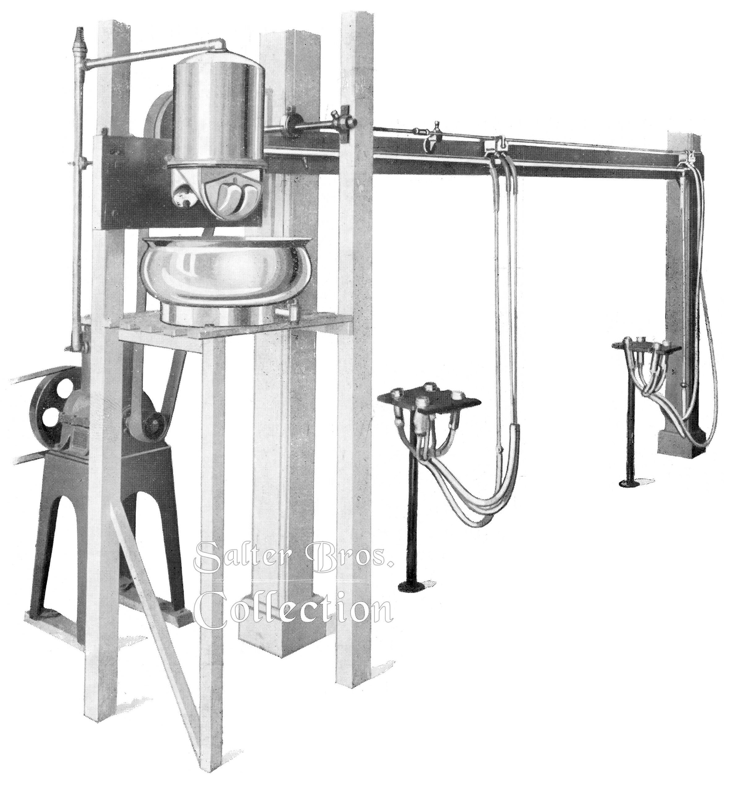
A Typical Two Cow Plant
There are many Milking Machines on the market, but not one has fulfilled every requirement of the Dairymen and Dairy Inspectors.
Most machines have been so complicated in their structure that they have been a trouble to clean thoroughly and to keep in a sanitary condition.
Consequently they have not been kept as clean as they should be, with the usual dissatisfaction of the Inspector.
In the Machine we are bringing to your notice, we have endeavoured to get rid of all matters of make and fitting, which have hitherto been the chief source of trouble, and we claim that the “Rutland” is so simple in its design and structure, and so easily cleaned, and kept clean, that if it is not the absolute ideal aimed at, it certainly is the nearest to it yet invented.
We beg to explain the various parts of the machine as under: –
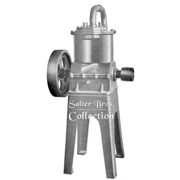
The Rutland Vacuum Pump
Totally Enclosed Vacuum Pump
Our Vacuum pumps are:
- Dust and Dirt proof
- Silent
- Wholly self-oiling
The splash feed throws Oil onto every part which requires lubrication, and no hand oiling is required.
Compact, a clear departure from the usual design, and well of the ground, it takes up no space, and throws no oil about.
It has an Oil Gauge to indicate the oil level.
The Rutland Milk Releaser
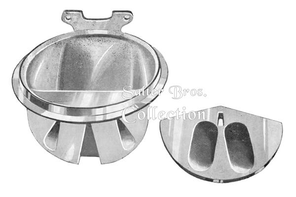
The Releaser: This is a circular Based plate, about eleven inches across and hollowed out into two compartments with orifices opening out to a Face Plate, which is set at the right angles to the Base Plate, and when in position is vertical. The Base Plate has a round raised edge, outside of which a rubber ring sits, on a lip, and on the rubber ring the bottom edge of the Dome rests to make a perfect vacuum joint. The raised edge of the Base Plate keeps the milk away from the rubber ring, and so guarantees that there is no bacteriation of the milk, through passing over or lying against the rubber.
The milk is discharged from the Face Plate by means of a valve fitting cloesly against the vertical plate, and having two compartments for receiving the milk through the orifices in the plate. The action of the valve is that of a pedulum, and as the valve is swung to and fro by the action of the eccentric the milk discharges from one compartment, while the other fills.
The valve moves backwards and forwards quick enough to guarantee a clearance through the Releaser of four gallons per minute.
This means that practically a continious flow of milk is kept up from the Releaser, and as there is no rubber to come in contact with the milk, the Releaser is absolutely sanitary in its working.
In order to ensure smooth filling, as the empty chamber swings back over the port to refill, an opening in the plate leading back on to the Base near the top of the chamber permits the air to be withdrawn from it before the milk enters.
The formation of the chamber is such that they have no corners, and are easily washed out.
The Rutland Pulsators
These are designed in duplicate, with two air tubes leading from the air intakes to the claw, and as the Pulsator valve is drawn backwards and forwards over the air inlets the air is drawn out of the 2 cups while it rushes in to form the squeeze in the other two.
Two cups are under suction, and in to a squeeze is taking place, at the same moment; but the Pulsar and the claw are so designed that the action is criss-cross; or suction is taking place on the far back and on the near front teats, while the squeeze is on the other two.
This action, continuously alternating, insures that the cups hold on much more firmly then otherwise could be the case; whilethe flow of milk is continuous from two teats at a time.
On the pulsar is a governor, which shortens or lengthens the suck or squeeze as desire to suit each cow, and as there is a pulsar over every bail, it means that each cow in the baies may be milked differently, according to whether she is hard or easy.
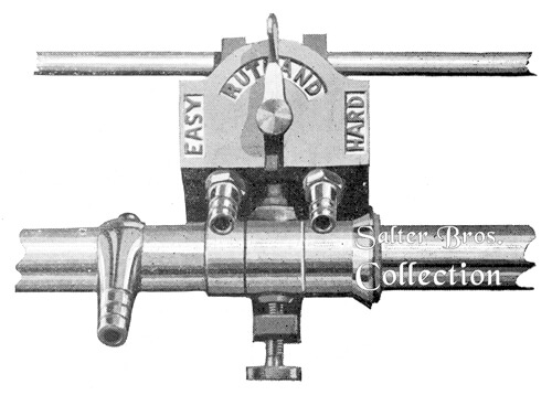
The Rutland Claw
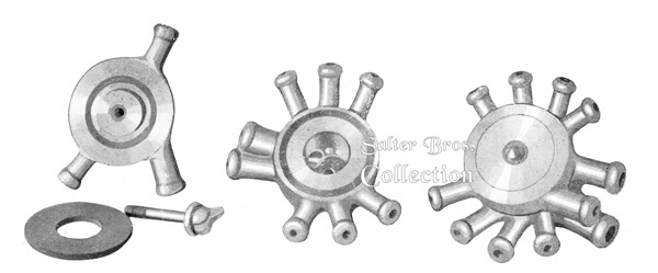
Claw – This is a rose or circular vehicle, fitted with four each air and milk nipples.
It has a centre chamber, into which the four milk nipples lead, and from which a large nipple conducts the milk away to the Releaser.
The walls of the claw are very thick, and the cap is solid, and about 3/4 of an inch thick.
In the wall of the lower portion, a circular groove is cut, into which the two nipples, diagonally oppose to each other, lead.
The cap of the claw is sufficiently thick to allow of a similar groove being cut in it on its underside, and in such a position that its underside, and in such a position that the outer edge of the groove in the cap corresponds with the inner edge of the groove in the body of the claw.
These air nipples are opposite position to those in the under part leading into the groove, while a larger nipple allows the air its inward and outward flow to and from the Pulsators, thus giving the criss-cross action so much desired.
The Rutland Simplicity Teat Cups
Cups – These are moulded with oval bodies, and are of such shape and size that the rubber inflations are pressed on by a ridge in the inside walls at the narrow part.
The object of this ridge in the oval is to control the action of the rubber inflation, when under the influence of vacuum.
Owing to the shape of the cup, the inflation must flatten parrallel to the walls.
No matter how the inflation is inserted, the coppalse must follow the outline of the wall.
This ensures that the life of the inflation will be three or four times longer than in the case usually.

Skim Milk or Water Pump
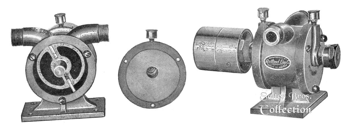
This is the most efficient little pump for lifting either skim milk or water; of very few parts, and these very strong, it is very durable. It will lift from ten to twenty gallons per minute, according to the speed at which it is run.
It can be placed on floor, wall or ceiling with equally good results.
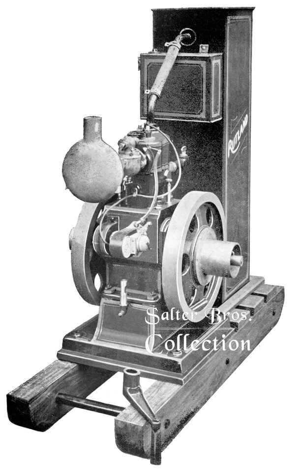
The “Rutland” 3 ½ H.P. Engine

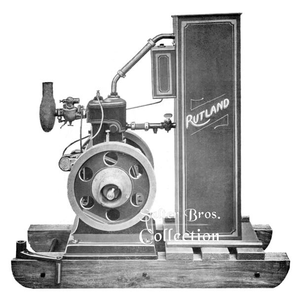
It is so compact that it takes up very little room compared with others, and its very compactness gives it greater strength and a longer life.
It is wholly splash fed, with an oil gauge to indicate the level of the oil in the sumph.
The bottle-oiler standing on the crankcase is used only for replacing the oil which is used by the engine when it is running, and does not oil any special parts.
Engine Information
Bearings
The main bearings are much longer than those on average engines, being four inches and five inches respectively, and are made of gun metal, grooved and fitted so that while the oil is distributed evenly over the surfaces of the bearings, a check groove stops the oil from working out on the wheels, and a return groove conveys the oil back into the sumph after it has passed through the bearings.
As a further check against leakage, a thick felt washer, similar to those used in motor cars, is fitted into a bevelled space on the outside of the bearing, and is held in position by a cap.
These felt washers stop all chance of any small leakage of oil which might pass the check groove.
Flywheels
The two flywheels are dished so as to bring the rims in over the bearings, and consequently there is no whip of the shaft, and they are balanced against the throw of the crank-shaft so perfectly that there is no vibration in the cylinder head, even when the engine is carrying a full load.
The oiling of the crankshaft is done by a trough, which is divided into two halves, and from the ends of which small copper pipes lead directly to the oil-holes in the inner ends of the bearings.
By these means, a steady flow of oil is automatically kept going as long as the engine is running and the oil is at its proper level.
All the other parts are fully supplied with oil by the splash.
The camshaft runs in gun-metal bearings, and the cams are keyed on so that they cannot possibly shift their positions, but they can be taken out and changed with very little trouble should need arise.
The cams are all case-hardened. The cylinder has a detachable head, held down to the crankcase by eight equally spaced studs.
This detachable head makes it easy to grind in the valves and to decarbonise the explosion chamber, and thus ensures stability.
The valves and tappets are totally enclosed and, so, thoroughly dustproof.
Governor
The governor has been specially designed for this engine, and is extremely sensitive. Each part fits to the other so perfectly that there is no loose play between them, and the governing screw is easily got at. The engine responds quickly to any alterations of this governing screw, and this means that the engine can be slowed down or speeded up easily and quickly.
Magneto
The magneto (Robert Bosch, Germany), is fitted to the side of the crankcase, and driven by gears from the camshaft. The Robert Bosch Magneto we find to be the most reliable. The magneto is fitted with an advance or retard adjustment.
Oiling System
The oiling is “splash feed” throughout. The bottle-oiler on top of the crankcase is for supplying oil to the sumph, as it is used up by the bearings, so as to keep the oil at a constant level, and does not specially oil any separate part.
The oil gauge is a sure guide to how the oil stands in the sumph, and the drip from the oiler can be regulated to a nicety.
The dip of the connecting rod splashes the oil into a trough, which gives a positive oil feed to the main bearings.
Carburettor
The carburettor fitted is a Schebler (Standard Model D), which we find to be the most efficient we have tried, and which is giving good satisfaction in all the engines already in use.
Silencer
This is a cast bottle silencer, without plates to get loose or clog, and which can be turned to allow the outlet to be led where desired, and so carry all fumes outside shed.
Cooling System
The cooling system is thermosyphon, and the tank is large enough to keep the engine cool at full load with continuous running.
Petrol Tank
This is of two-gallons capacity, with gravity feed to the carburettor.
Pullies
Special iron pullies, which are fitted on to flywheels, and thereby eliminate the whipping strain, are supplied with the engine, but ordinary pullies can be fitted if so desired.
Base
The base is broad, and extends beyond the flywheels, thereby ensuring stability.
Cranking
The crank handle fits well over the crankshaft, and is free and safe. The magneto has a catch-holder, with three positions, to enable it to be retarded or advanced.
Dustproof
The whole engine is made as dustproof as possible, thus ensuring not only long life but also the smallest amount of cleaning.
Duplicate Parts
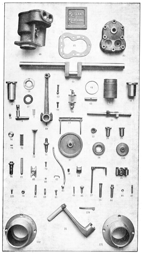
All parts are standardised, and duplicate;, guaranteed to fit are kept in stock.
As shown in the illustration in the booklet, each engine is sent out on skids made of 6 x 4 jarrah, strongly bolted together, unless otherwise ordered, but portable engines on wheels can be provided equally as well.
The trolley, with iron wheels, costs £12 extra.
Each engine is assembled, with tank. on heavy jarrah skids, as per illustrations, thus making it semi portable.
Engine Information
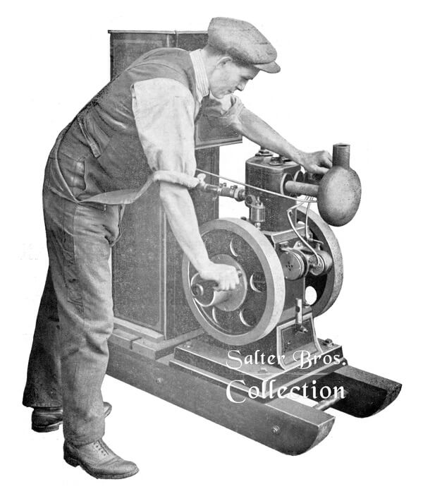
Illustrating the Proper Method of Starting.
Left hand partly closing Air Intake to make strong starting mixture.
