Rider-Ericsson Hot Air Engine
Rider Engine Design
THE OPERATION of the Rider Engine is briefly as follows: The compression-piston, C. first compresses the cold air in the lower part of the compression cylinder, A, into about one-third its normal volume.
When, “by the advancing or upward motion of the power-piston, D, and the completion of the down stroke of the compression-piston, C, the air is transferred from the compression-cylinder, A through the regenerator, H, and into the heater, F. without appreciable change of volume. The result is a great increase of pressure, corresponding to the increase of temperature, and this impels the power-piston up to the end of its stroke.
The pressure still remaining in the power-cylinder, and reacting on the compression-piston, C, forces the latter upward till it reaches nearly to the top of its stroke, when, by the cooling of the charge of air, the pressure falls to its minimum, the power piston descends, and the compression again begins.
In the meantime the heated air, in passing through the regenerator, has left the greater portion of its heat in the regenerator plates, to be picked up and utilized on the return of the air toward the heater.
We have several styles of water-pumps for use in connection with these engines. Generally, however, the engine is placed near the source of water-supply, and is furnished with the Rider Rolling-valve Pump bolted to the cooler, as shown below.
The pump is made in two pieces. The upper or main part contains the delivery-valves, and also the barrel, which is a seamless drawn brass tube.
The Pump
The lower chamber, to which the suction-pipe is attached, contains the suction-valves, and is bolted, as shown, to the main part.
The bucket is provided with two reverse-cup leathers; the rod passing upward through the stuffing-box is connected to an arm on the cold piston, as may be seen by referring to the cut of the engine,.
The pump is held to the cooler by two bolts, which are long enough to go through and secure the bonnets over the valves.
")
")
Rider Engine, with flat valve pump (for heavy suction)
and furnace for Gas, kerosene or coal.
")
Rider engine, with deep well pump and furnace
for wood or bituminous coal.

Rider Engine, with rolling valve pump attached
and furnace for Gas, Kerosene, or Coal
")
Double acting rolling valve pump for light suction

Front and rear views of Rider engine with furnace for gas, kerosene or coal and showing smoke pipe connection.
The engine on the left has a flat valve pump for heavy suction, the one on the right has a roller valve pump for light suction.
Ericsson Engine Design
THE ERICSSON Hot-air Pumping-engine is a single-cylinder engine in which are two pistons, one called the main or air-piston, which receives and transmits the power, and the other called the transfer piston, the office of which is to transfer the air contained in the machine alternately and at the proper time from one end of the cylinder to the other.
The cylinder is provided at its upper end with a water-jacket, through which all the water passes on its way from the well to the tank.
This keeps the upper end of the cylinder cool, while the
lower end is exposed to the fire and becomes as hot as it is practicable to make it.
By the peculiar arrangement of connections between the air- and transfer-pistons, the proper relative motions between these pistons are obtained.
The operation is as follows: After the lower end of the cylinder has been sufficiently heated, which takes only a very few minutes, the engine must be started by hand by giving it one or two revolutions.
The air contained in the machine is first compressed in the cold part of the cylinder; it is then transferred to the lower end, where it is instantly heated and expanded, thus furnishing the power.
This engine, like all other hot-air engines, is only single-acting.
The momentum of the fly-wheel continues the revolution until it receives an additional impulse by the repetition of the above mentioned conditions, which occur once in every revolution.
The same air is used continuously, and is cooled, compressed, heated,
and expanded in the regular order and without noise.
The furnaces of the Ericsson Engine are arranged for burning any kind of fuel. When gas or any liquid fuel is used the Furnace and fuels shown (opposite) is used; but when coal and Fuels wood are used a very heavy cast-iron furnace, thoroughly lined with the best fire-brick and provided with a dumping grate, is used, as shown below.
Either style of furnace may be substituted for the other without removing any other part of the machine.

Ericsson engine with furnace for Gas, kerosene oil or gasoline showing arrangement of oil tank, burner, connecting pipe and valve.


Ericsson Engine with furnace for gas or kerosene or gasoline, showing arrangement of oil tank burner, connecting pipe and valve.

Showing relative sizes of five, six, eight and ten inch Ericsson Engines.
In cases where the water is too far below the surface
In cases where the water is too far below the surface of the earth to be drawn up by the ordinary surface-pump, it becomes
necessary to use a pump particularly adapted and designed for these cases.
We furnish with these machines with deep-well pumps, such as shown in the engraving, which may be inserted into these deep wells, either open-dug wells or artesian, or drilled wells.
This deep-well arrangement is intended to be used only on the 6-, 8-, and 10-inch engines.
When the water is within a few feet of the surface—say, 20 feet or less—it is preferable to use the pumps shown on page 4; but when the water is further from the surface than 20 feet it becomes necessary to use a deep-well pump attachment. In this case the engine must stand close to the well and in such a position that the pump rod will go directly from the engine down to the pump.
When it is possible to do so, these pumps should be lowered into the water, so as to avoid any work on the suction side.
The pipe which connects the pump with the engine is made sufficiently large for the pump-rod to work inside of it, and also to allow sufficient space for the water to pass upward. It is generally preferable to cut this discharge-pipe into short lengths— say, from 8 to 10 feet—as they are much more easily handled.
The pump-rod is made of pipe or wooden rods, as may be deemed best. These sections of pipe and rod are screwed together as they are lowered down, it being unnecessary to go into the well.
Extreme depth to which pumps may be lowered:
5-inch Engine, pump not lowered on this size.
6-inch Engine, pump lowered . . . 30 feet.
8-inch Engine, pump lowered . . . 60 feet.
10-inch Engine, pump lowered… 135 feet.
Figure 1 (below) shows side elevation of the Improved Ericsson Engine applied to deep well pumping, and with coal- or wood furnace.
Figure 2 (below) shows the deep-well arrangement enlarged.
A— Pump-rod. B Pump-rod Guide. C—Stuffing-box. D Pump- pipe. F—Pump-cylinder. G Suction valve. H—Strainer. J—Delivery-valve.


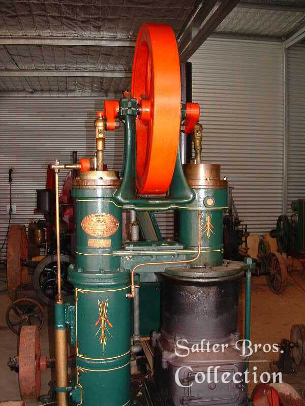
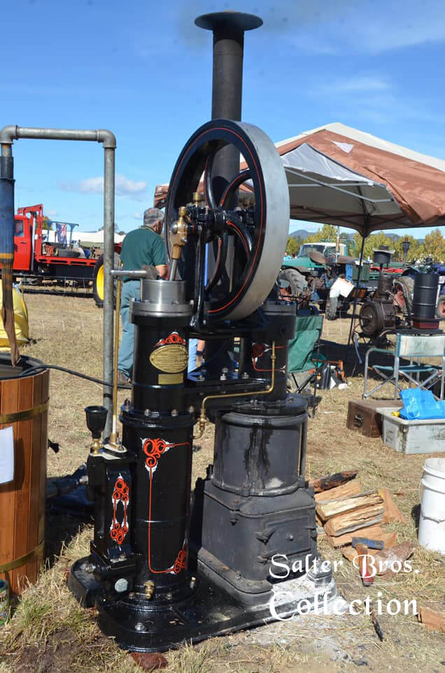
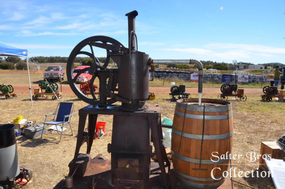
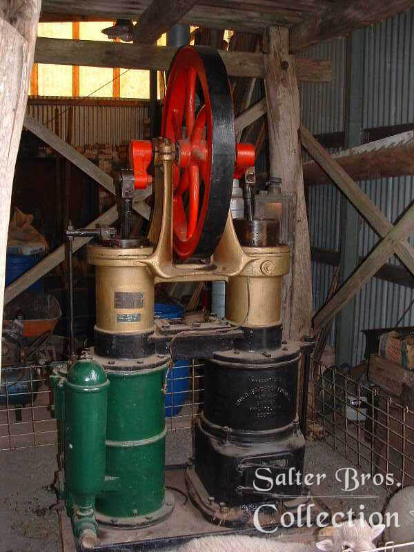
Gallery
These are various Rider-Ericsson photos that I have taken over the years at different rallies around Australia.